One the most basic things an electronics enthusiast should know is the difference between AC vs DC.
No, we’re not talking about a hard rock band, we’re talking AC vs DC with regards to electricity.
Some of you may already know this. Even if you’ve been dabbling in electronics for a while and think you have this figured out, I highly recommend reading this whole post as there are some things that may surprise you.
One of the easiest ways to explain the differences between AC vs DC is to treat each one separately and delve into some details about each.
Toward that end, we’ll start with DC first because it’s a bit simpler to explain and most of your creations will use it.
AC vs DC: Direct Current
Electric current (or a voltage, as voltage and current are proportional) can be classified as direct current (DC) or alternating current (AC).
Direct current flows in one direction only, while alternating current changes direction periodically.
In the land of electricity, another word for direction is polarity.
But what do we really mean by this?
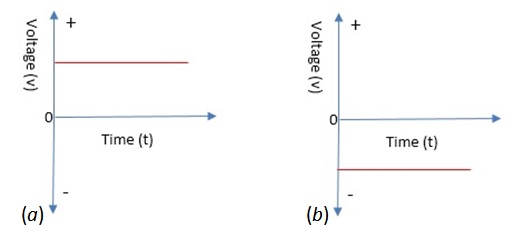
If we were to plot the voltage of an ideal battery versus time, we’d have a flat line, as you probably already know. With a given DC source, this line can either lie on the positive end of the y-axis or the negative end, but not both.
To see what I mean, take a gander at the simple pictures below.

Figure 1: positive and negative DC voltages
The red horizontal lines represent DC voltage. On the left, we see a positive DC voltage (it could also represent a current if we labeled the y-axis current instead of voltage).
Notice how the line lies above the x-axis, which represents time, and how it will never dip below the x-axis — if we assume a steady-state voltage – even if we drag the x-axis out to infinity.
However, part (b) of the figure shows the voltage lying below the x-axis, which makes it a negative DC voltage.
In both parts, the line either dwells above or below the x-axis, but never actually crosses the x-axis, even if we watch this very exciting “waveform” for an infinite amount of time.
AC vs DC: a DC Surprise
To most of us, it’s plainly obvious that a flat horizontal line on a graph represents a DC voltage.
Become the Maker you were born to be. Try Arduino Academy for FREE!

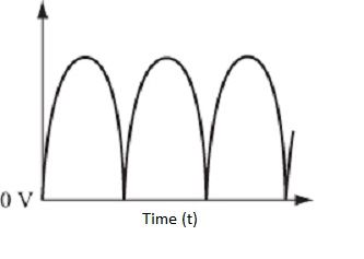
But what about the figure below? Is this AC or is it DC?

Figure 2: AC vs DC: is it AC or DC?
If you said DC, you’re right.
Figure 2 depicts what’s known as pulsating DC.
Even though this graph does not depict a flat horizontal line, it does not go negative at any point (assuming it remains steady-state and periodic).
Pulsating DC varies periodically from some minimal voltage (zero in this case) to some maximum voltage, back to minimum and then repeats.
By periodic, we mean that the waveform repeats itself at regular, predictable intervals. I’ll spare you the mathematical definition of periodic.
Remember, pulsating DC does not vary from a positive to a negative voltage or vice versa. It stays either positive or negative along the whole x-axis, regardless of the amplitude or wave shape.
This type of voltage/current occurs at the output of certain battery chargers, and also at the output of a full-wave bridge rectifier which is part of a circuit that converts AC into DC.
Remember, whether pulsating or steady (like the flat line) direct current is current that flows in only one direction. Figure 3 below shows this concept in a simple circuit.

Figure 3: a simple circuit
Using electron flow (for more about electron flow vs conventional current flow see the post), current would flow from the negative terminal of the battery through the resistance to the positive terminal.
This direction does not change unless we change the polarity of the source. If we reverse the polarity of the battery by flipping it around (negative end now on top), current flows the opposite direction of the arrow.
Either way, the current (and voltage) is DC because it will never alternate from positive to negative.
AC vs DC: What is AC?
Alternating current, or AC, is electric current first in one direction for a period of time and then in the reverse direction for a period of time.
Direct current can only change in magnitude, but alternating current can change in both magnitude and polarity.
Most of us are familiar with the AC power supplied to our homes.
Some of us may be familiar with the alternator in our vehicle that produces power. An alternator produces AC power (hence the name) before it is rectified and put to use to charge the battery and power the vehicle’s accessories.
The power at the receptacle in your home as well as the power created by the alternator in your vehicle (before rectification) comes in the form of a sine wave.
Sine is short for sinusoidal which, as we can see from a graph of the mathematical/trigonometric sine function, describes the shape of the wave.
The figure below depicts a typical sine wave you’d find at the receptacle in your home.

Figure 4: a typical AC sine wave
The AC power in your home is sinusoidal in nature because it is generated by rotating conductors in a magnetic field. If we take one cycle of the sine wave above and fold the negative half over to the left, we see that the resulting shape is somewhat circular in nature.
By cycle, we mean one alternation from zero, up to some maximum positive value, back to zero where it crosses the x-axis, then down to some minimum negative, then back to zero again where the cycle ends.
In figure 4, there is a small “x” where the first cycle ends and the second cycle begins.
Since we are rotating something in a circular motion (with a generator) to produce AC power, it should be no surprise that the sine wave is shaped the way it is. And, since there are 360 degrees in a circle, each cycle of the sine wave also goes through 360 degrees.
AC vs DC: More Detail on AC
We know that alternating current gets its name because it alternates from positive to negative, but what does that really mean?
During one half-cycle electrons flow in one direction. Then, they switch and flow the opposite direction during the other half-cycle.
Figure 5 from Introductory DC/AC Electronics illustrates this.

Figure 5: how alternating current moves
In part (b) of the figure, we can see a typical sine wave. Part (C) shows how electrons move during the positive alternation and part (d) shows how they move during the negative alternation.
So, electrons in an AC circuit will move back and forth about a fixed point.
To clarify, consider the simple circuit in figure 3, only there is an AC source there instead of a battery.
Now, imagine that you’re very small and can “sit” in the middle of the resistor and see electrons flowing by.
For one instant, they pass you in one direction, in another instant, the opposite direction.
In fact, if you counted the number of electrons that slip by you during each alteration, you’d see that not only is it the same number each direction, but if you could tell each individual one apart from others, the same electrons would keep passing you — first in one direction, then the other.
Still want more clarification? This fantastic video from Khurram Tanvir should do the trick.
The video shows the basics on how an AC generator works.
It also shows how electrons move back and forth about a fixed point. Notice the needle on the voltmeter moving back and forth (with 0 as the fixed point) as the generator spins creating the sine wave.
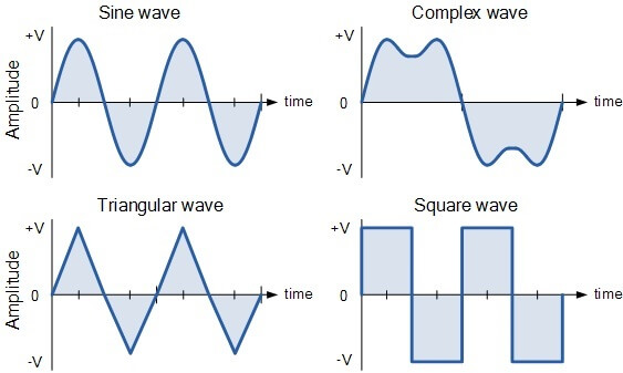
One important fact about alternating current is that it doesn’t have to be sinusoidal.
Figure 6 depicts 3 other types of AC waveforms along with a sine wave.

Figure 6: other types of AC waveforms
The square wave should look familiar; you’ll see similar waves in digital circuits. Triangular waves are good for testing certain types of devices, like some amplifiers. Complex waves often crop up, too. They may or may not be desirable, depending on the circumstances.
For example, a sine wave with noise injected into it may look like the complex wave in the figure above. Or, an AM radio signal may take on a similar form. One is desirable while the other is not.
Regardless of their shape, they all have one thing in common: they’re positive for some period of time, then negative for some period of time.
AC vs DC: A Little Math
I know the “m word” is making some of you groan right now while others are rejoicing, but I promise – it won’t be that bad.
The mathematical description of a typical (non-pulsating) DC waveform is stupid-easy:
V (t) = V
Where t is time.
In other words, it’s a flat horizontal line and V is the voltage that remains constant throughout time (that’s why it’s graph is a horizontal line).
The description of a typical AC waveform depends on the shape, but for simplicity’s sake we’re going to assume a sinusoid.
Mathematically, an AC sinewave is technically described by the equation below.
v (t) = V sin (ωt + φ)
Where ω = 2πf.
That equation may be more familiar if you’re an engineer or electronics tech.
The lower-case omega (ω) is the frequency in radians rather than Hertz. Since most hobbyists aren’t super familiar with radians, the equation can be changed to a more familiar form.
v (t) = V sin (2πft + φ)
What follows is a break-down of what each part of this equation means.
t represents time.
v (t) is a function of how the voltage varies or changes with time. In other words, v (t) changes as time changes. The stuff on the right of the equal sign describes how this change looks.
V is the amplitude of the sinewave.
2π is a constant used to convert radians, which is an angular frequency (radians per second) to Hertz, the unit you’re probably more familiar with.
f is the frequency in Hertz, or cycles per second. In a 60 Hz circuit, one cycle takes 1/60 of a second (this is the period of the wave which describes how long one cycle lasts. In general, the period T = 1/f, so one cycle of 60 Hz power lasts for about 17 ms). Conversely, there are 60 cycles in one second in a 60 Hz circuit.
Φ is the phase of the wave. This is a measure of how far the wave is shifted with respect to time and is somewhere between 0 and 360 degrees. Once a sinusoid is shifted 360 degrees, it’s as if the shift never happened. The wave is the same because there are 360 degrees in a circle. In other words, if I were to draw a circle with a compass, once I rotated it 360 degrees the circle would close and start again at 0 degrees.
You may be wondering how this fits in with the 120 V coming from a receptacle in your home.
In the U.S., AC power has a peak amplitude of 170 V (120 V is the RMS value) and the frequency is 60 Hz. We’ll assume no phase shift.
With this information, we can write
v (t) = 170 sin (2π60t)
to mathematically describe the voltage coming from the wall.
Don’t try this, but if you were to view the AC power in your home on an oscilloscope, you’d see a 60 Hz sine wave with a peak amplitude of 170 V.
If we graph this equation on a graphing calculator or computer, the same thing would show — no scope required.
Most of My Gadgets Use DC, Why Does the Power Company Supply AC?
If you have some experience in electronics, you likely know the answer. If you’re new, it may not be obvious.
Most things that plug into the outlets in your home convert the AC feeding it into DC. This includes your TV, computer, DVD player, Wi-Fi router and more.
There are a few good reasons why the power company supplies AC power rather than DC power.
- With AC power, you can easily step the voltage up or down with a transformer. Doing the same with DC is more complex. This allows the utility to use high voltage and lower current, which is more efficient. Wires have a resistance, which becomes significant if they’re miles long. Remember, Power = I2R; more current means more heat lost in the resistance of all those wires. That’s money wasted. So instead of high current they use high voltage (while keeping the current low), which can easily be reduced later.
- It is much easier to convert AC to DC than it is to convert DC to AC.
- The generators the power company uses work by spinning conductors in a magnetic field. This naturally give rise to an AC sinusoidal output, as we already know. Some generators can output DC, but they are more expensive and more complex. Also, AC generators are usually larger, meaning they can generate more power.
As an interesting side note, the battle between AC vs DC power distribution settled in the 1890’s with AC as winner. This is why we use it today.
However, new technology has made a DC grid more feasible and efficient. There are a few small areas around the world that are testing this idea. Suffice it to say, it’ll be a while before the whole grid converts to DC, if it ever does.
Rockin’ Out with AC vs DC
There is so much more to the world of AC and even DC than we can cover in one post.
For example, we did not talk about transients (DC), nor discuss AC related things like RMS (root mean square), peak value, peak-to-peak value, or phasors in much (or any) detail.
Looks like a job for a future blog post!
Until then, comment and share what topic you would like to see covered in a future post. It might just show up.
Become the Maker you were born to be. Try Arduino Academy for FREE!

References:
- Cook, Nigel P. Introductory DC/AC Electronics, 4th Ed. Prentice Hall, 1999. Print.
- Alexander, Charles K. & Mathew, Sadiku N.O. Fundamentals of Electric Circuits, 2nd Ed. Mc Graw Hill, 2004. Print.
Electronics Tips & Tutorials Sent Directly to Your Inbox

Submit your email & you'll get:
- Exclusive content that I don't put on the blog
- The checklist 10 mistakes all electronics enthusiasts make (& how to avoid them)
- And more!
That’s good to know that AC can also change in polarity as well as magnitude. I would think that would make it a bit more useful than DC, but I am sure that there are situations for both. I’ll have to learn a bit more about both of them so that I can make the best use out of my electricity.