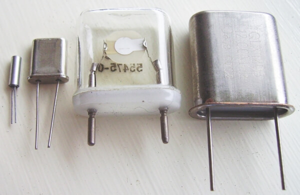
The crystal oscillator is everywhere. The need for precise frequency control sets the stage. Crystals ensure not only accurate timing for microprocessors and microcontrollers, but also in setting the frequencies of any radio or wireless device.
Sure, you can make an oscillator out of capacitors, inductors, and resistors but their limitations are severe. Things like time, temperature, and other physical conditions can wreak havoc on their accuracy, causing the output to drift off frequency. A crystal oscillator is much more stable. We’ll delve more into that soon.
Quartz is the material of choice for most crystals, however, cheaper (albeit less accurate) ceramic resonators can sometimes take the place of quartz in a crystal oscillator.
Crystal oscillators operate on the principle of something called the piezoelectric effect. Let’s go into a bit of detail about the piezoelectric effect.
What is the Piezoelectric Effect?
First demonstrated in 1880, the piezoelectric effect is an interesting phenomenon. Materials which exhibit a piezoelectric effect are part of a larger class of materials known as ferroelectric ceramics.
Quartz is a crystalline material. Some crystalline materials have unit cells (think of these as the smallest possible “crystal” within the larger crystal, like splitting a grain of salt to its smallest size before it splits into single atoms) that are not symmetrical. This asymmetry causes small electric dipoles to form.
To get an idea of what the piezoelectric effect looks like on an atomic level, consider the picture below.

In this material there will be an excess of positive charge on one end and negative charge on the other. This is due to the polarization, or electric dipoles we talked about earlier.
Section (b) of the picture shows the crystal with a mechanical force applied to it. We can also see that the distance d between the dipoles is smaller. This changes the charge density at the ends of the crystal, which induces a voltage difference between the ends if they are insulated from each other.
Section (c) shows an electric field (voltage) applied across the crystal. This causes the dimensions of the crystal to change (distance d is larger in the picture) in the direction of the electric field. Because the positive plate of the battery makes the top more positive and negative plate makes the bottom more negative, the dipoles are stretched. The negative end of the dipoles are attracted to the positive charges and vice versa.
Unfortunately, you cannot look at a crystal with the naked eye and see the size change; this happens on microscopic scales.
In summary, the piezoelectric effect is an electromechanical effect by which mechanical forces on a ferroelectric material (like quartz) produces an electrical response, or electrical forces a mechanical response. Some other common applications for piezoelectric materials are small speakers and igniters on grills and lighters.
Crystal Oscillator Basics
Now we know that crystals mechanically “vibrate.” The greatest vibration occurs at the crystal’s natural resonant frequency. This is determined by the physical dimensions and by the way the crystal is cut.
Some standard values for crystal oscillators are 100 kHz, 1 MHz, 2 MHz, 4 MHz, 5 MHz, and 10 MHz. The full range of values spans from 10 kHz to 30 MHz.
Manufacturers know how to cut the quartz to optimize its performance to meet certain metrics like frequency, stability, etc. Some common cuts are the X-cut, Y-cut, CT-cut, AT-cut and there are others. Though you likely won’t need to concern yourself with this, it’s good to know.
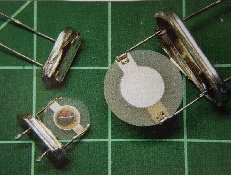
Crystals usually consist of a quartz wafer mounted between two electrodes. A metal can protects the whole package.
The picture below shows some crystals with the metal can removed. Opening the protective can contaminates the quartz, which ruins the crystals, but it’s interesting to see the inside nonetheless.

Crystal oscillators are desirable because they are very stable with time and temperature and also highly selective. They have a very high Q, so the resonant frequencies of the crystal are sharply defined. Recall that the quality, or Q, of a circuit is equal to the bandwidth divided by the center frequency.
You can build a simple crystal oscillator with just a transistor and a crystal, but crystal oscillators that come in one package (like an IC) are more common these days. They’re also cheap, some less than $2.00 in quantities of one. With these units, the crystal is already wired into the on-chip oscillator. All we need to do is apply a DC voltage, then either a sine wave or rectangular wave pops out the other end.
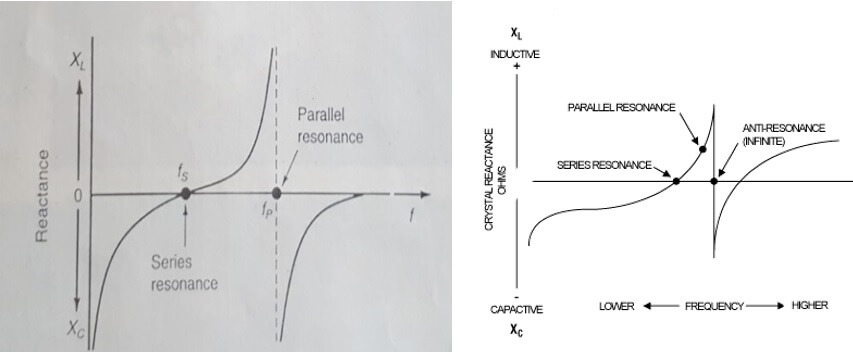
Quartz crystals have two usable resonant frequencies associated with them. One is FSERIES which — you guessed it — is a series resonance. The other is FPARALLEL and is a little higher in frequency. It also corresponds to a maximum impedance, whereas FSERIES corresponds to a minimum impedance.
Become the Maker you were born to be. Try Arduino Academy for FREE!

Note that there isn’t such a thing as a “series cut” or “parallel cut” crystal. Rather, think of series and parallel as modes of operation instead of a “cut” of some sort. All quartz crystals are capable of resonating in both modes. Crystals (regardless of how they’re cut) are made to be closest to their design frequency with the correct capacitance applied (external to the crystal) and when using the correct mode.
We know that quartz crystal oscillators are very accurate. While a typical RC oscillator has an accuracy of about 0.1% and a typical LC oscillator has an accuracy of about 0.01% (at best), crystal oscillators boast accuracies that range from 0.01 – 0.001 percent.
A crystal’s error is expressed in parts per million or ppm. For example, a 10 MHz crystal with a deviation of 200 ppm (rather high) has an error of (200/1,000,000) x 10,000,000 = 2kHz, which is a maximum error of 0.02%. This is an example of a “lower-end” crystal.
Types of Crystal Oscillators
There are many types of crystal oscillators on the market today.
The simplest one is the ordinary XO variety which comes in a fixed frequency with an accuracy of a few hundred parts per million. These crystals are good for non-critical applications like embedded controller clocks.
Then there is the TCXO crystal. TC stands for temperature control. Since crystals are subject to slight frequency changes with temperature, these find their home in more critical applications. Special circuitry inside the oscillator consisting of a thermistor in a feedbaclk loop that drives a varactor corrects the frequency when it drifts. You may find this type in your cell phone.
Yet another type is the VCXO, or voltage controlled crystal oscillator. Applications for this type of crystal include phase-locked loops and frequency multiplication or synthesis.
Another type is the oven-controlled crystal oscillator or the OCXO. This oscillator is built into a thermally enclosed package with a small heating element that cycles on and off under closed loop control to maintain a constant temperature. These find their way into even more critical applications like cell base stations and telecommunications networks.
The Quartz Crystal Oscillator Equivalent Circuit
The quartz crystal equivalent circuit is a series-parallel RLC circuit like the image below.

The inductor LM is typically very high, ranging from 0.1 H to 1 H. Some people refer to CM as the motional capacitance and it is very low, in the femtofarad range. CS is simply the parasitic capacitance between the two terminals of the quartz. It is usually a couple of picofarads.
The unusual values of LM and CM give us some insight into the accuracy and high-Q of the crystal. To recapitulate, the Q of a circuit is the bandwidth over the series resonant frequency. The extreme values of these components can yield quartz crystals with Q values of 100,000 or more.
If you try to build a similar circuit out of discrete components, you’d run into trouble. Try finding a 1 H inductor with a parasitic capacitance below one femtofarad and you’ll see why.
Series Resonance and Parallel Resonance
At the series resonant frequency, LM and CM cancel leaving only the remaining series resistor, which is usually 100 ohms or less and determines the impedance of the crystal. The series resonant frequency is independent of the parasitic capacitance CS.
Parallel resonance occurs when the inductive reactance of LM and the capacitive reactance of CS are equal, creating a classic LC tank circuit. This frequency is a bit higher (usually at least 1 kHz) than the series resonant frequency, but still close to it. Because of the tank circuit, the impedance of the crystal reaches its maximum value at this point.
The image below specifies FPARALLEL as FP; you may also see this written as FA where the “A” means antiresonant. Technically, the term FP is reserved for when an external load capacitor is used since this will drop the resonant frequency a bit (more on this in minute). FA is the parallel resonant frequency without the external capacitor. Because of this, some of the plots you see may contain an FS, FP, and an FA. Don’t let this confuse you. Either way, the values are essentially the same thing with little difference (roughly 0.1%).
Looking below, we can see how the crystal behaves like a capacitor below FSERIES and more like an inductor above FSERIES. We can also see how it is purely resistive at FSERIES, where it crosses the horizontal axis. Notice also the vertical asymptote at FPARALLEL which suggests that the crystal’s impedance is very high (ideally infinite) when operated in this mode. It’s also interesting to view the graph on the right where we can see the impedance dip at FSERIES and then peak at FPARALLEL.

As we now know, in parallel mode the parasitic capacitance of CS influences the resonant frequency. Because CS is the capacitance between the terminals of the crystal, any external capacitor will influence the resonant frequency, as it will be in parallel with CS. Crystals that are meant to be used in parallel mode should show the value of the external capacitor in the specs. The crystal won’t behave as expected if you use a different capacitor value.
Speaking in Overtones
Earlier, we learned that crystal oscillators are available in frequencies from 10 kHz to 30 MHz.
This is only a half-truth though.
The design of some crystals allow them to work in overtone mode where the frequency can go as high as 250 MHz or above.
The overtone frequencies are usually close to three, five, or seven times the fundamental resonant frequency. It’s important to note that these overtones are not electrical harmonics of the two resonant frequencies, rather they are mechanical overtones (hence the name) where the crystal vibrates in more complex ways. In other words, the third overtone frequency is not exactly three times the fundamental frequency, though it can be close.
No Hocus Pocus
Now we know that crystals aren’t just for jewelry aficionados or psychics. In fact, it’s hard to find an electronic device these days that doesn’t contain the often-misunderstood components.
Hopefully, this post has removed some of the mystery surrounding crystals and crystal oscillators.
There’s a lot more to say about crystals and the circuits and oscillators that contain them. A future post may go into more detail about crystals and the circuits that use them.
How often do you use crystals in your projects? Comment and let us know.
Become the Maker you were born to be. Try Arduino Academy for FREE!

Crystal Oscillator References:
- Smith, William F. & Hashemi, Javad. Foundation of Materials Science and Engineering, 4th Ed. McGraw-Hill, 2006. Print.
- Horowitz, Paul & Hill, Winfield. The Art of Electronics, 3rd Ed. Cambridge University Press, 2015. Print.
- Lacoste, Robert. “Let’s Be Crystal Clear.” Circuit Cellar June 2008: 70-77. Print.
Electronics Tips & Tutorials Sent Directly to Your Inbox

Submit your email & you'll get:
- Exclusive content that I don't put on the blog
- The checklist 10 mistakes all electronics enthusiasts make (& how to avoid them)
- And more!
Nice write-up Brian. Lots of info in a condensed packge!
Glad you enjoyed it!
Hi Brian,
i HAVE A FAULTY dvr WITH A SMALL PILE OF BROWN GUNK AT THE END OF THE LITTLE CLOCK CRYSTAL 32.768 kHZ
IS THAT COMING OUT OF THE CRYSTAL? is THERE SOME “STUFF” IN THE CAN WHICH COULD LEAK OUT? oTHERWISE IT MUST BE FROM A SMD CAPACITOR NEARBY. WHAT DO YOU THINK? AND HOW CAN I NON DESTRUCTIVELY TEST THAT CRYSTAL?
( The website field has some microcapture microscope images in a zip file )
Could it be a dab of glue? I’ve seem them glued down before.
Indeed, this is a good write-up, and I’m very glad to see you explain that “series” and “parallel” are circuit topologies instead of special crystal cuts. Some schematics would help show why these are so named, and would also show how in series resonance the crystal is essentially purely resistive whereas in parallel resonance the crystal looks like an inductor.
It can also be instructive to derive the resonance equations given the “motional” equivalent capacitance and effective inductance in resonance with the load capacItance (including “holder“ capacitance). thEse more advanced topics probably don’t belong in an introduction, though your treatment is considerably more detailed than most.
Just one clarification: The “TC” in TCXO stands for “temperature-compensated”. Ovenized crystal oscillators (OCXOs) are temperature-contRolled.
Thanks for your insight and I’m glad you liked the post. Crystals are one of those things you don’t learn a lot about in school and one topic that I’d like to know more about. In a future article, I’m sure I’ll revisit these fascinating devices again and perhaps cover some of the topics you suggested.
Very instructive article!
I would like to make a clear case for a quartz ocsilator, you said ” Opening the protective can contaminates the quartz, which ruins the crystals” can you tell me the reasons for that?
Aside from damaging the crystal and delicate connections/parts inside the case by opening it you’ll introduce impurities like dust, pollen, hair, mold, etc. Try it if you don’t believe me