Since their inception in 2005, Arduino development boards have become a favorite among hobbyists, makers, and experimenters.
Of all the different incarnations, the Uno remains one of the most popular.
In fact, if you’ve been dabbling in electronics for more than a few minutes or have worked with microcontrollers, chances are you’ve used it before or have at least heard of it.
A while ago, I wrote an article about using the Arduino vs a stand-alone microcontroller (like the ATmega328 that powers the Uno or a PIC).
They both have their pros and cons, so if you’re interested check out Getting Naked: Working With Naked Microcontrollers vs Trainers Like Arduino.
Though many of us have used the Arduino Uno, most of us seldom think of how it works or what’s under the hood. We’re going to take a closer look inside the Uno and see what makes it tick.
Actually, this will likely be the first of a series of posts about the inner workings of the Uno and the nuances of working with it. I may not write them in order (I may write about other topics before posting part 2), but they’ll eventually come.
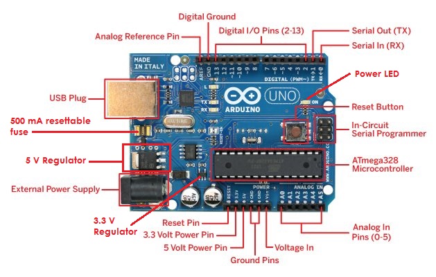
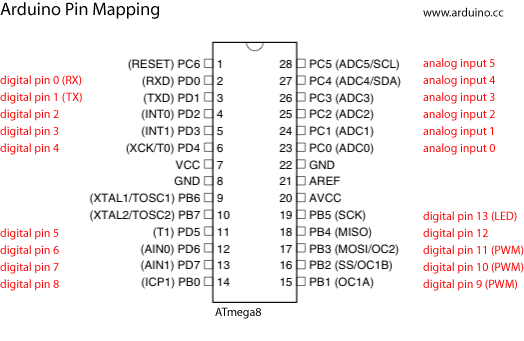
If you’re looking for the Arduino Uno and ATmega328 pin-out, see figures 1 and 2.
Now, let’s have a closer look inside the Arduino Uno.
Why is the Arduino so Popular?
Made in Italy, the Arduino showed up on the scene in 2005. Since then, there have been various incarnations of the board including the Duemilanove (2009 in Italian), the Diecimila (which means 10,000 in Italian to celebrate the making of the 10,000th one), the Mega 2560, and more.
The boards are very versatile and can handle most common things microcontrollers can do, and the price is low.
Then there’s the fact that the software to program it is free and can be used on Windows, Mac, or even Linux.
The hardware and the software are both open source, so others can take the designs and improve them without worrying about licensing fees.
There are many shields that are available which easily attach to the board adding functionality.
And finally, they’re great for experimenting and prototyping projects (though my Getting Naked post explains why you may want to go for a stand-alone micro instead).
Quick Arduino Overview
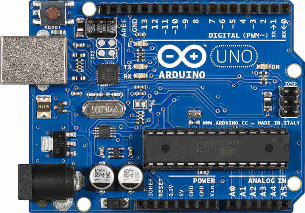
Refer to figure 1, which shows the Arduino Uno.

Figure 1: the Arduino Uno board
Obviously, the rectangular thing in the lower right is the brains of the Uno, the ATmega328.
The power jack on the lower left is a 2.1mm center positive barrel connector. Above that, we can see a USB Type B jack for connecting the Arduino to a PC.
Become the Maker you were born to be. Try Arduino Academy for FREE!

A series of 28 female pin headers allow you to connect other things to the Arduino and are at the top and bottom. These headers are separated into three groups. The digital pins are at the top. On the bottom left we have the power pins, and the analog pins dwell on the lower right (notice the small gap between them). Out of the 28 pins, 20 are for I/O.
The six analog pins can also serve as general purpose digital I/O. Out of the 14-total digital I/O pins, six can be used to generate PWM (pulse width modulation) signals.
The Arduino Uno also supports basic communications standards like TTL serial, SPI, I2C, and 1-wire.
Two of the inputs support hardware interrupts. They trigger on either a LOW, a rising edge or falling edge, or a change in value via software.
The oval-shaped silver object in the middle left is the 16 MHz crystal.
To the right of the power jack are two 47 µF capacitors. We’ll take a closer look at these in a future post.
Directly above the jack lies a 5 V low dropout voltage regulator. Directly above the capacitors closest to the microcontroller we can see a 3.3 V low dropout regulator. It lies near two surface mount capacitors.
Powering the Arduino is an often overlooked, but a very important part in the effective use of the device. Many spurious errors are actually power issues. We’ll go into more detail on properly powering the Arduino in a different post.
A Closer Look at the Arduino Uno
An Arduino Uno board measures 2 1/8” x 2 ¾”. The SMD version is slightly different but most people want the ability to easily replace the ATmega328 microcontroller if they accidentally kill it. If you’re new to Arduino, electronics, microcontrollers, or some combination of the above I’d skip the SMD version and grab the one in figure 1.
The operating voltage of the Arduino Uno is 5 V which can come from either a USB cable and your PC or some external source.
The recommended input voltage range is 7 – 12 V. You should try to keep that number closer to 7 V if you can as the small regulator will dissipate any excess energy as heat and can become very hot. We’ll go into more detail on this issue in another post.
The Arduino Uno contains two regulators. The 5 V regulator can theoretically provide up to 800 mA and the 3.3 V version can source 50 mA.
What Else is Onboard the Arduino Uno Board?
Aside from the microcontroller, the Uno has a few other main points of interest.
There is an integrated USB-to-serial communications chip for downloading programs or “sketches” from your PC and for serial communications back to the PC for debugging and monitoring.
This chip is the small black box above the 16MHz crystal in figure 1.
The USB link sports a 500 mA resettable fuse to guard against any possible damage to your PC. When you plug your Arduino into a USB port, the board takes its power from that port. In USB 2.0, the current a port is capable of sourcing is usually 500mA. USB 3.0 ports can source anywhere from 900 mA to 3 A depending on the type of port.
The analog pins connect to an internal 10-bit analog-to-digital converter (ADC). All the I/O pins can function as digital outputs and can sink/source up to 40 mA.
Next to the analog pins lie the power pins which provide access to both the regulated and unregulated power supplies.
Arduino Pin-Out and Microcontroller
The ATmega328 chip on the Arduino isn’t empty, it comes pre-loaded with a small bootloader for use with the Arduino integrated development environment (IDE).
One nice thing about the Arduino is that you can use it to program other ATmega328 chips if you were to build a project with the stand-alone microcontroller.
To do this, you’d program the chip, remove it and then insert it into your own circuit. All it needs is 5 V, a 16 MHz crystal, and two 22 pF capacitors.
There are a few more minor details on this and it’s something that I personally have not done, but I know its possible. Perhaps we’ll revisit the topic in another post once I get a chance to play with it.

Figure 2: ATmega328 pin-out and Arduino I/O pin mapping
Feast your eyes upon figure 2, which shows a pin-out diagram of the ATmega328.
One of the first things to note is that the ATmega328 pin numbers are different from the Arduino Uno pin numbers. This is important!
The labels black labels outside the chip are the primary function names for each of the pins, while the parenthetical labels on the outside are any alternative uses for the pin, if any are available. The writing in red shows the ATmega328-to-Arduino pin mapping.
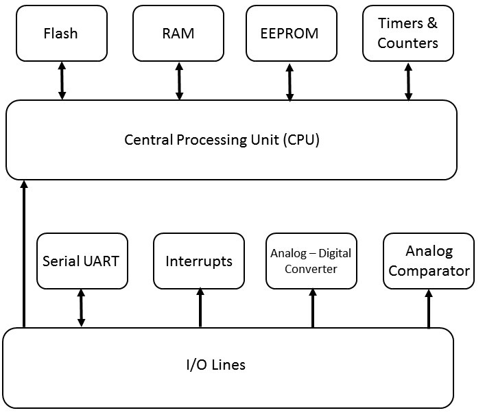
Figure 3 shows a simplified block diagram of the ATmega328 microcontroller.
The I/O block is the 20 analog and digital pins. The six analog pins go to the ADC, which has a resolution of 4.9 mV because there are 1024 steps (remember, the ADC is 10-bits and that 210 = 1024) and when we divide 5 V by 1024, we get 4.9 mV per step.

Figure 3: ATmega328 simplified block diagram
The two external interrupts that the chip supports map to Arduino digital pins D2 and D3.
There was a time when the analog comparator was not accessible through the Arduino IDE.
Personally, I have not tried to use this feature myself, but some quick searching seemed to suggest that there are now ways to use the comparator with the Arduino IDE.
The analog comparator will trigger an interrupt when voltage on one input equals or exceeds the voltage on another input. This could come in handy for certain projects. For example, say you want a fan to come on when the air reaches a certain temperature.
A Few Words About Arduino Sketches
As of this writing, the current version of the Arduino IDE is version 1.8.3.
The Arduino comes with a Java-based IDE with a fully featured text editor. Once you write a sketch, it needs to be compiled which is referred to as verifying in the Arduino ecosystem.
Sketches are written in a language similar to C, though a sketch itself is not completely compatible with C.
There’s no main() function for one thing, at least not one that’s visible. It’s hidden from view and added for you when you compile or verify your sketch.
The sketch downloads to your Arduino via a USB cable. This process is automatic as the bootloader that resides in ATmega328 detects when a sketch is arriving.
The sketch takes residence in the 32 Kb of flash memory inside the ATmega chip. This memory can endure at least 10,000 read/write cycles, so you’re unlikely to wear it out any time soon. The Arduino also sports 1 Kb of electrically erasable programmable read only memory (EEPROM) which is non-volatile. Finally, there is also 2 Kb of RAM available which is volatile.
All Arduino sketches need two parts at a minimum: the setup() and loop() functions. These two functions take no arguments — so the parentheses are empty — but they still need to be there.
They appear as follows:
Void setup() { any code would go here
}
Void loop() { any code would go here
}
If you’re familiar with C, you know that void in front of the functions simply means that the function does not return a value when it’s done processing.
These two functions are a requirement and the Arduino IDE will report an error during compile if any of the two are missing.
Often, the makers of the board will release updated versions of the IDE. When they do, it’s a good idea to download them and install them. You can keep multiple versions of the Arduino IDE on your PC and switch between them if you want, but this isn’t something you should need to do often. If you do install the latest IDE, be sure to take a gander at the readme file for the latest changes.
More Inner Workings of the Arduino Yet to Come
Many of you have used the Uno in your projects and experiments, but now you have a little more detail on how the board and the brains (the ATmega328) work.
Future installments of this series will go into more detail about powering the board, a very important but often overlooked issue. We’ll also take a closer look at the digital and analog I/O pins, as there are some “gotchas” hiding there.
Meanwhile, comment and let us know about your latest Arduino experiments, projects, and endeavors!
Become the Maker you were born to be. Try Arduino Academy for FREE!

Electronics Tips & Tutorials Sent Directly to Your Inbox

Submit your email & you'll get:
- Exclusive content that I don't put on the blog
- The checklist 10 mistakes all electronics enthusiasts make (& how to avoid them)
- And more!
Leave a Reply