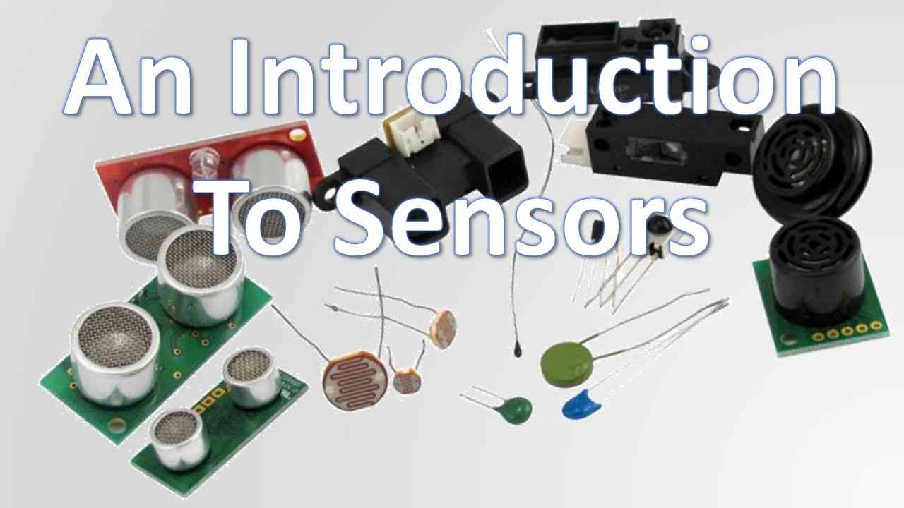
In the land of electronics, there are many different types of sensors.
If you start dabbling in electronics, it won’t be long before you end up needing/wanting to measure some sort of quantity like temperature, speed, light level, distance, sound, humidity etc.
This is especially true if you work with Arduino, RPi, PICs, or any sort of platform or microcontroller.
These days, there are many different electronic sensors to choose from. Given the pace at which technology advances and the myriad of sensors available, those new to electronics often find themselves confused about sensors and how to apply them.
What type of sensors do I need? How do I use this particular sensor?
The above are common questions hobbyists often ask themselves.
This post will take a stab at answering the first of those two questions and maybe a bit of the second question.
We’re going to cover some of the most common types of sensors you’re likely to see and use in your projects.
We won’t go into any great detail on how a particular type of sensor works (I’ll probably dedicate a complete post to each particular sensor as time goes on). Instead, we’ll introduce each type of sensor and give a quick explanation of what it’s for and the basics of how it works.
Let’s talk about the types of sensors you’ll be working with.
Common Types of Sensors
Temperature Sensors
The desire to quantifiably measure temperature dates back hundreds, perhaps even thousands of years. Of course, accurately measuring temperature wasn’t feasible thousands of years ago (as far as historians and archaeologists know), but you can be sure the desire was there.
Thermometers were in use as early as the 1600’s. By 1742 all the temperature scales we’re familiar with — except the Kelvin scale, were developed. The Kelvin scale was born in 1848.
Today, there are a variety of types of sensors one can measure temperature (and even humidity) with. Let’s start with the simpler ones first.
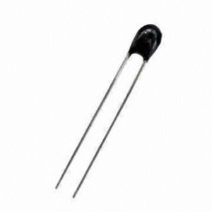
A thermistor is simply a type of resistor that varies resistance with temperature. For example, if I want to build a circuit that turns on an attic fan when it reaches a certain temperature, I may use a thermistor. It’s a simple and elegant solution. Figure 1 depicts a typical thermistor.

Figure 1: a typical thermistor.
Thermistors have been around since the 1960’s and are made of metal oxides of semiconducting materials.
They come in two flavors: negative temperature coefficient (NTC) and positive temperature coefficient (PTC). The resistance in a PTC thermistor increases with temperature while the resistance in an NTC thermistor decreases as temperature increases.
To use one with an Arduino or microcontroller, you’ll need to use the analog pins or the analog to digital (A/D) converter on your micro. You can also go analog and use a thermistor with op amps.
Another type of sensor for temperature measurement that you’re less likely to use is the thermocouple. Gas water heaters and furnaces usually use thermocouples to sense the flame of the pilot light. A thermocouple is really just two dissimilar metals fused together. When the metals heat up, a phenomenon known as the Seebeck effect causes a voltage to appear at the device’s terminals. This voltage can be translated into a temperature. Figure 2 depicts a thermocouple.

Figure 2: a thermocouple like this may reside in your gas water heater or furnace.
Thermistors and thermocouples only sense temperature, but other devices like the DHT11 and the DHT22 sense both temperature and humidity in a small, easy to work with package.
The DHT22 is more expensive than the DHT11, but sports greater accuracy.

Figure 3: a DHT11 on a breakout board. The breakout board makes it easier to use the sensor with platforms like Arduino, but you can also buy the sensor without the board.
You may notice from figure 3 that the breakout board has one less pin than the sensor itself. This is because one of the pins on the sensor is a “no connection” or NC pin which doesn’t connect with anything inside the sensor. It’s just there for stability and to add strength when soldering it to a circuit board.
Become the Maker you were born to be. Try Arduino Academy for FREE!

Inside, the DHT sensors are complex and even contain their own IC or integrated circuit. Discussing the innards of the DHT sensors is beyond the scope of this tutorial, but data sheets which go into more detail are available.
More Types of Sensors: Mechanical Sensors
Accelerometers
Acceleration is a change in velocity with respect to time. You feel acceleration when you floor the gas pedal of your car. You also feel an acceleration (or deceleration) when you jam on the brakes to slow down. In both instances, your velocity is changing with respect to time.
Acceleration is an essential parameter for many applications including vibration, shock, and more.
Accelerometers act like a damped mass on a spring — and this is actually what they really are.
Figure 4 diagrammatically depicts the guts of a typical accelerometer.

Figure 4: crude representation of the inner workings of an accelerometer.
In the figure above, we can see a mass M which connects to a spring on the left and a damper on the right. Of course, accelerometers are much smaller than figure 4 leads one to believe.
Presently, the most popular manufacturing technology for accelerometers (as well as many other types of sensors) is MEMS. MEMS stands for micro electro-mechanical system. MEMS sensors are small, easy to make, and inexpensive. They also sport low power consumption with solid performance. As the word micro implies, the guts of such sensors are very small so they can fit conveniently in a chip.
These types of sensors come in two flavors: active and passive. Active accelerometers do not need an external power supply and output their own electrical signal without it. Piezoelectric accelerometers are a member of this category. If you’re unfamiliar with the piezoelectric effect this tutorial on crystals may help.
Passive accelerometers do require some sort of external power. Piezoresistive and capacitive sensors fall into this category.
When picking an accelerometer some specs to look out for are acceleration range (measured in g’s), frequency response, and bandwidth.
Gyroscopes
Gyroscopes are also MEMS devices.
Large gyroscopes have been around in ships, airplanes, and spacecraft for a while and are used as stabilization devices. Figure 5 shows the purely mechanical type of gyroscope you may be familiar with. This is not the type you’ll be using in your robot.

Figure 5: a large, purely mechanical gyroscope.
The ones you’ll be using are much smaller.
Explaining the workings of a gyroscope in detail requires a decent understanding of the physics behind it which is beyond the scope of this introductory tutorial on sensors.
For those who do have a background in physics, here is a quick overview of how they work. A gyroscope uses the principle of conservation of angular momentum. To put it simply, a body in motion stays in motion unless it’s acted on by an external force. The principle of Coriolis acceleration is at work in the small gyroscopes hobbyists use. This makes it possible to etch them in silicon and package them in chip form. It also makes them cheap.
Inside the typical hobbyist-grade gyroscope, there is a fork-like structure which is in constant back and forth motion. It is held in place with piezoelectric crystals. Whenever this arrangement tilts, the piezo crystals experience a force in the direction of inclination due to the inertia of the moving fork. The crystals then produce a current because of the piezoelectric effect.

Figure 6: a representation of the inside of a MEMS gyroscope. The bars in the middle are the fork that moves back and forth.
Often, you’ll find accelerometers and gyroscopes in the same package as one unit. An example of this is the GY-521 which hobbyists often use with Arduino. Figure 7 shows a typical GY-521 unit.

Figure 7: a GY-521 gyroscope/accelerometer with header pins. You’ll need the headers to make the board easier to work with.
Types of Sensors Part 2 Coming Soon
The original intent was to also discuss other sensor types in this tutorial such as acoustic sensors and optical sensors.
However, I don’t think I can do them justice with the amount of space remaining, so I’m making this tutorial a series.
Next time, we’ll get an introduction to acoustic and optical sensors. And, there may even be a third part to this series covering other types of sensors you may encounter. No promises on that, but we’ll see…
Meanwhile, drop a comment and tell us about the sensors you use the most. Or, tell me about which sensors you’d like to see me cover in a tutorial. Then maybe there will be a part 3…
Become the Maker you were born to be. Try Arduino Academy for FREE!

Electronics Tips & Tutorials Sent Directly to Your Inbox

Submit your email & you'll get:
- Exclusive content that I don't put on the blog
- The checklist 10 mistakes all electronics enthusiasts make (& how to avoid them)
- And more!
Hi there, just became aware of your blog through Google, and found that
it’s really informative. I’m gonna watch
out for brussels. I’ll be grateful if you continue this in future.
Lots of people will be benefited from your writing. Cheers!
good, nice, beautifully images and INFORMATION website
Nice article! I look forward to part 2, this part was informative, well written, easy to understand, and gave light to the subject addressed. Many times articles are written that are difficult to grasp. Not so here!
Thank you for taking the time to put it together.
Glad you liked it Bill. Part 2 is now here! https://www.circuitcrush.com/intro-acoustic-optical-sensors/