Greetings fellow geeks, we’re back again with a practical mini-project you can bust out on your bench and use right away. This time I have a short video to go along with the post and also a transcription of the video (scroll down for video) afterwards.
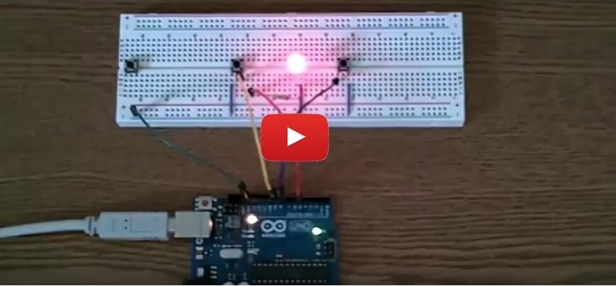
In the video, I use 2 push button switches and an Arduino Uno to turn an LED on and off.
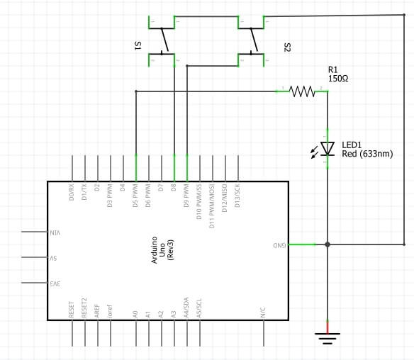
After the video, but before the transcription, you’ll find a schematic and a breadboard circuit diagram (courtesy of Fritzing).
I know, some of you may be thinking who cares, it’s just turning an LED on and off…
However, this type of circuit can come in handy for controlling many things besides LEDs. Things like motors on robots, LCD displays, relays, and more come to my mind right away.
Plus, if you’re new to Arduino or programming, you may not know how to do this simple exercise. Even if you’re an Arduino/programming pro, I’m sure you can extend this to other things (which may require extra circuitry).
Take about 4 minutes, watch the video, then leave me a comment and let me know what you’re currently working on and if you’d like to see more videos like this.
This is one of my first videos, so if the picture and/or audio aren’t quite studio quality I apologize. Improvement is a continuous process and one I usually welcome.
One more thing: be sure to subscribe to my YouTube channel as I’ll be making more videos soon.
How to Use an Arduino & Push Button Switches to Turn an LED on/off
Ever dreamed of being Iron Man, having the ability to build anything, anytime? Try Academy for Arduino!


Figure 1: circuit layout diagram.

Figure 2: circuit schematic.
Want to get started with Arduino & microcontrollers? You’ll love the new course How to Get Started With Arduino in 1 Day or Less!
Transcription of How to Use Arduino & Push Button Switches to Turn an LED on/off
Note: I did not transcribe this myself. Please excuse any spelling, grammar, punctuation errors or omissions.
Hello and welcome to circuit crush TV.
Today I want to show you guys how to turn a LED on and off with an Arduino Uno and a couple of push button switches. Now, this is pretty-simple and some of you may be thinking well who cares it’s just a LED. There are a ton of other uses for a set up like this. So, let’s say you have a robot that you have a couple of bumper switches on and when the switch hits you want it to change directions. This’ll come in handy for that kind of application and a lot of other things. So, don’t think that this is just limited to blinking a LED or turning the LED on and off rather with a push of a button. You can use this to turn anything on and off whether it’s a motor, a fan, an LCD display, it’s just pretty much limitless to what you can do with this kind of circuit.
Now I already wired it up, and I want to quickly go over these circuits. You notice there is two push buttons, here and here and this third one off to the side. I have that there because the orientation of the switches is pretty important. There are four pins, and some of them are connected internally. So, if you don’t put them in the breadboard in the right orientation it won’t work. And you see we have a little gap here, and I made sure that there are two legs on one side and two on the other. Now you might be wondering which two legs are connected and which are not. To figure that out I grab my Ohm meter here and we can see that those two are connected and these two are not unless I push the button then it connects. That’s the right way to orient these push button switches.
Really quickly we have, of course one ground wire here right to the Arduino ground pin and we have these three blue jumper wires. They are grounds for the push button switches and the cathode of this LED will be at ground. And then we have a 150 Ohm resistor on the anode. That value really isn’t critical anything from 120-220, 250 depending on how bright you want it, should work. But you want to have some resistor, at least 100. I wouldn’t go any less than that. And then we have that LED connected to pin 5 or digital pin 5.
Also, we have one the switches with this yellow jumper going to pin 9 and this blue jumper here on the other switch going to pin 8. So, I already wired this thing up and I already written a simple program to make this thing work. I’m going to demonstrate it and then we’ll get into the program a little bit here. So, let me plug in the Arduino here, and the code should be uploaded, let’s see. Okay so on and the other button off, on, off. Pretty simple stuff.
So, let’s cut on over and take a quick look at this code, it’s real simple.
Okay so here we can see the simple program on my computer screen here that makes this thing tick. All we’re doing is initiating a couple of pins as you can see up top. We are designating the pins as output one of them and then the other two are input pullups, and then we just go into the loop. It’s just saying, look, if one button is pressed, if this button is pressed make this pin high. If the other button is pressed, make the other pin low, which turns the LED on and off. So, this is real simple stuff guys.
I know it’s a short video, hopefully you enjoyed it. Go ahead and leave me a comment and let me know what you think and let me know what you guys are working on.
Ever dreamed of being Iron Man, having the ability to build anything, anytime? Try Academy for Arduino!

Electronics Tips & Tutorials Sent Directly to Your Inbox

Submit your email & you'll get:
- Exclusive content that I don't put on the blog
- The checklist 10 mistakes all electronics enthusiasts make (& how to avoid them)
- And more!
Leave a Reply