How Diodes Work – An Introduction
This post explores the basics of how diodes work.
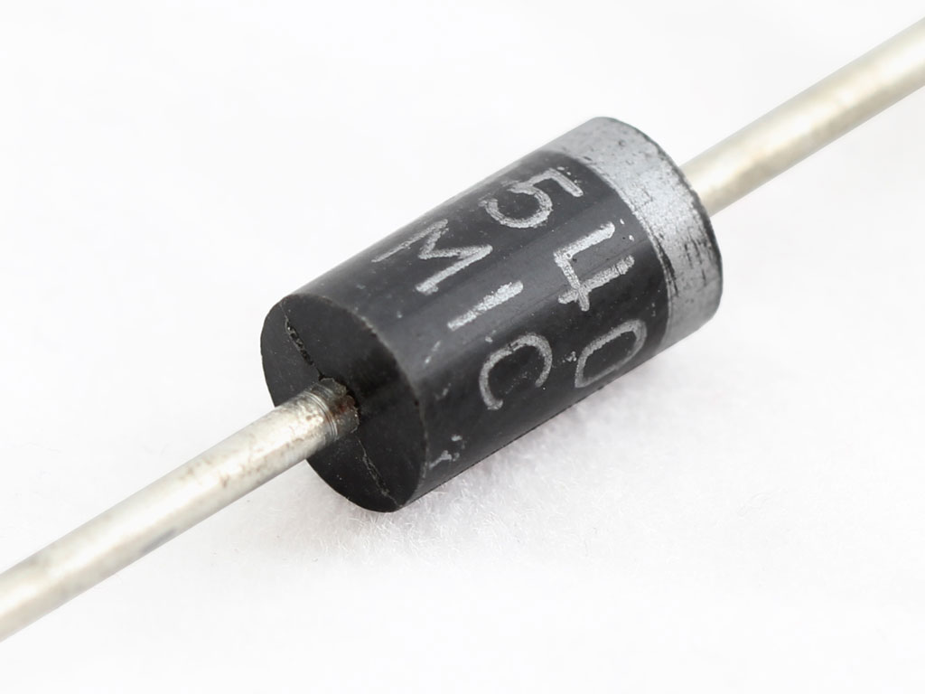
A diode is the most basic useful semiconductor device. It has two leads and acts as a one-way gate for electric current. Diodes have a multitude of uses, some of which we’ll touch on later.
We’ll start our tutorial on how diodes work with a very quick overview of basic semiconductor physics. This will serve as the basis for which all diodes work.
How Diodes Work – Semiconductor Physics 101
Semiconductors are neither good conductors or insulators. However, their resistance can be controlled by a process called doping to either increase or decrease the resistance. This is why semiconductors are so useful.
A pure semiconductor must be modified by doping to give it desirable qualities. Doping is adding impurity atoms to the material.
There are two main types of semiconductor material in electronics: n-type and p-type.
The doping of the silicon (or germanium) will determine if the material is n-type or p-type.
N-type and P-type Material
To produce an n-type semiconducting material, the manufacturer will add varying amounts of arsenic, phosphorous, antimony, bismuth and other pentavalent elements.
Pentavalent means that there are five electrons in the outer most shell (valence shell) of the atom. When a pentavalent substance is added to pure silicon, four of the five electrons will be bound the silicon atoms, while the fifth will be a free electron. The figure below illustrates this.

That fifth electron in the picture above is not part of the covalent bonds (like the other four are) and requires a small amount of energy to break free.
To produce an p-type semiconducting material, the manufacturer will add varying amounts of aluminum, gallium, boron, indium and others.
The scenario is similar to the one in the picture, only instead of an extra electron we now have an extra hole.
Holes are like positive charges. Another way to think of a hole is the absence of an electron. Looking at the diagram above, imagine that the As atom is now an Al atom. All electrons in the valance shell of the Al atom will participate and bind to the silicon atoms. But because Al (and the other materials) are all trivalent atoms, there will be an empty space or a “hole” where the fourth electron would normally be.
Holes appear to move in the opposite direction of electrons. This is because every time an electron moves into a hole, it creates another hold behind it.
How Diodes Work: The Depletion Region
N-type and p-type material are of little use by themselves.
Together, they form a P-N junction.
It’s important to note that the manufacturer does not create separate p-type and n-type material and then glue them together. Rather, a single piece of silicon would have each half doped accordingly.
The area on either side of the diode junction is the depletion region (a.k.a. space charge region). This area is depleted of free electrons and holes.
This occurs when the two materials meet. Electrons from the n-type side rush over to fill empty holes on the p-type side. This action “uncovers” positive charges in the n-region because holes are left behind when the electrons migrate to the other side.
Similarly, holes “move” from the p-side over to the n-type material and uncover negative charges. Refer to the figure below.

Though the whole diode is electrically neutral, the charges in the depletion region set up a barrier potential. For silicon, this is about 0.7 V (at room temperature) and for germanium it’s about 0.3 V. This barrier potential is also known as the “diode drop” and is why there is a drop of 0.7 V across a silicon diode in an energized circuit.
How Diodes Work: Are You Biased?
Because of the barrier potential, a voltage of a certain amplitude and polarity is necessary for conduction (the 0.7 V for silicon). These voltages are the bias voltages. Bias voltages control the width of the depletion region. This controls the resistance of the P-N junction, and the amount of current that can pass through the diode.
Diodes can operate in either forward bias or reverse bias mode. Forward biasing a diode allows current to flow and reverse biasing a diode blocks current from flowing. Let’s discuss this a bit more.
Diodes: The Practical Side
All the above describes the theory on how diodes work. But, chances are you won’t be fabricating your own P-N material or diodes at your bench.
Become the Maker you were born to be. Try Arduino Academy for FREE

The schematic symbol for a typical diode is below.

The anode is the positive side (p-type material) and the cathode is the negative side (n-type material). An easy way to remember this is that the line on the cathode side resembles a negative sign that has been flipped on its end.
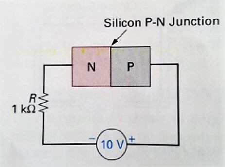
When a voltage source connects to the diode with the negative end of the source on the cathode and the positive end on the anode, the diode is forward biased. In other words, making the cathode more negative with respect to the anode forward biases the diode.
Earlier, you may have come to the conclusion that a diode works like a switch.
This is true.
When you forward bias a diode, the “switch” closes and current flows through it, if the potential applied is enough to overcome the barrier potential set up in the depletion region.
The simple diagram below illustrates this.

If we want to know the current flowing through the diode, we can use the formula
I = (Vsource – Vdiode) / R
In this case, the diode is silicon, so we get
(10 – 0.7) / 1k = 9.3 mA
How Diodes Work: Reverse Biasing
When we reverse bias a diode, we make the cathode more positive with respect to the anode. This is like turning the 10 V source shown in figure 4 180 degrees. The positive end of the source would now be at the cathode and the negative end is at the anode.
Doing this will increase the width of the depletion region. This happens because free electrons in the n region are drawn to the positive terminal of the source, leaving behind holes (positive charges). Also, the electrons from the negative terminal of the source are attracted to the holes in the p region. They fill the holes in this region near the junction creating negative ions.
Note that a very small current known as a leakage current still flows after reverse biasing a diode, but since it is on the order of nanoamps or smaller it is negligible.
If you’re having trouble picturing this, the image below can help.

The widening of the depletion region will continue until the barrier potential matches the potential of the voltage source, as shown in the picture.
Diode Voltage-Current Characteristics
Refer to the picture below for the following discussion.

The top right quadrant of the graph shows the diode in forward bias (as seen in the simple circuit in the inset) and the lower left quadrant shows it in reverse bias.
Notice the point on the x-axis (positive direction) where the current suddenly rises. This is about 0.7 V for silicon diodes. This also resembles the shape of a human knee and is therefore known as the knee voltage. The knee voltage is just another name for the diode’s internal barrier potential. This is why we see a huge spike in current once the voltage reaches 0.7 V. Of course, a given diode can only take so much current, so it will burn out if the current increases too much, as we can see in the graph.
Looking at the reverse characteristics of the diode in the bottom left quadrant of the graph, we can see that diodes does its job and limits current flow to almost zero until we reach 50 V.
This point also resembles a knee.
The spot on the reverse voltage scale at which the diode breaks down and conducts is known as the breakdown voltage. This voltage, which varies depending on the type of diode, is also known as the peak inverse voltage (PIV). Just as in the forward case, if current continues to increase the diode will eventually burn out.
Notice that curve as a whole is non-linear. We assume a barrier potential of 0.7 V for silicon diodes, but the exact value involves considering the non-linearity of the diode (and ambient temperature) and uses exponentials and more complicated math.
I won’t bore you with the exact equations, but when using them you’d find the value to be sufficiently close to 0.7 V. The constant voltage drop model (assuming 0.7 V for silicon) is fine for most applications. Also, using the constant drop model enables rapid analysis of circuits employing diodes. If you were to use the exponential model, you’d want to use a SPICE program.
There are a few other models like the piecewise linear model which attempts to linearize parts of the curve, the ideal model which assumes no barrier potential, and the small signal model which is useful for finding the signal component of the diode voltage.
Perhaps we’ll talk more about these models in a future post. For now, know that the constant drop model is the one you’ll usually use.
Practical Applications of Diodes
One of the most common applications for diodes is rectifying AC into DC. The power supply on your bench likely employs a bridge rectifier consisting of four diodes.
Diodes also find a home in clipping circuits (a.k.a. limiters) which clip parts of a waveform and clampers which add a DC component to a waveform. Clampers are also known as DC restorers.
Voltage multiplication is another common use of diodes (think of a stun gun).
A special type of diode known as a Zener diode operates in the reverse breakdown region where it can serve as a simple voltage regulator. A voltage regulator ensures a certain voltage output regardless of what the load is like.
Diodes also make good transient suppressors. When working with relays, it is usually a good idea to connect a diode across the coil to absorb the transient that occurs when the coil’s magnetic field collapses.
And there are other uses for diodes, some of which we’ll revisit in more detail in the future.
How Diodes Work: That’s a Wrap
Diodes are the most basic semiconductor device with a ton of uses.
There are also many different types of diodes out there that you’re likely to run into or at least hear about.
Some of these include the Zener, the Schottky, PIN diodes, tunnel diodes, varactors, LEDs, laser diodes, and even more.
What clever uses have you found for diodes? Comment and tell us!
Become the Maker you were born to be. Try Arduino Academy for FREE!

References:
- Cook, Nigel P. Introductory DC/ACs Electronics, 4th Ed. Prentice Hall, 1999. Print.
- Sedra, Adel S. & Smith, Kenneth C. Microelectronic Circuits, 5th Ed. Oxford University Press, 2004. Print.
I never knew that bias voltages are required to control the width of the depletion region. I just find it fascinating to imagine electrons being channeled in a certain way to conduct a current. I’ll have to watch out for the polarity in the future!
Having problems with my cub cadet tractor blowing fuses.I found a diode in the fuse circuit and this might be the problem.The problem is INTERMITtent with the fuse blowing.knowing that temperature will effect the diode may be the clue